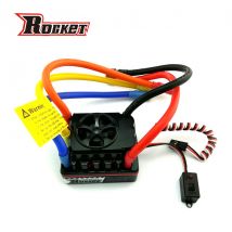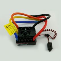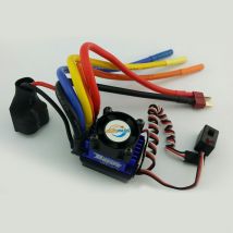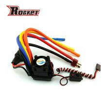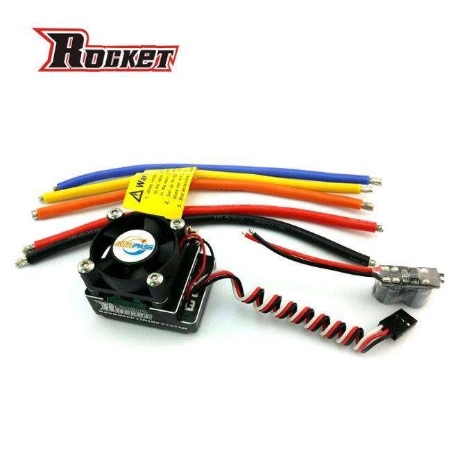
ROCKET 120A Competition ESC with TURBO function for 1/10 RC Car
Shenzhen Surpass Tech Co.,Ltd
ROCKET Turbo Series Brushless Speed Controller for 1:10 &1:12 scale Car or Truck
Thank you for your purchasing the ROCKET Brushless Electronic Speed Controller (ESC). The ROCKET electronic speed controller is specifically designed for operating Sensored/Sensorless brushless motors. High power systems for RC model can be very dangerous and we strongly suggest that you read this manual carefully. ROCKET Model have no control over the correct use, installation, application or maintenance of these products, thus no liability shall be assumed nor accepted for any damages, losses of costs resulting from the use of this item. Any claims arising from the operating, failure or malfunction etc. will be denied. We assume no liability for personal injury, property damage or consequential damages resulting from our product or our workmanship. As far as is legally permitted, the obligation for compensation is limited to the invoice amount of product in question.
Features:
l Enhanced throttle response, excellent acceleration, linearity and driveability
l Using advanced PC interface to set up or update the firmware
l Using LCD program card to make adjustments.
l Throttle curve and punch rate adjustment
l Dynamic boost timing and turbo timing adjustment
l Brake curve and brake rate adjustment
l Dynamic running data log
l Multiple protection features: Low voltage cut-off protection, over-heat protection and throttle signal loss protection
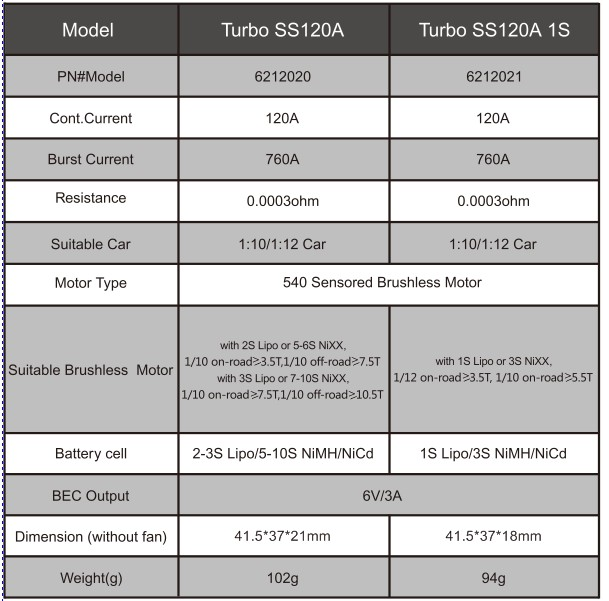
Turbo Series Brushless System specification:
* Sensored Mode
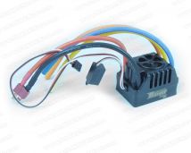
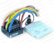
When using a Sensored Brushless motor, the Blue motor wire A, Yellow motor wire B and Orange motor wire C of the ESC must be connected with the Sensored motor wire A,B,C respectively. It is necessary to connect the Sensor wire to the “Sensor” socket on the ESC. Don’t change the wires sequence optionally.
* Sensorless Mode
When using a Sensorless Brushless motor, the Blue motor wire A , Yellow motor wire B and Orange motor wire C of the ESC can be connected with the motor wires freely. If the motor runs in the opposite direction, please swap any two wire connections.
* Connection to the Receiver
Black wire RX-
Red wire RX+6.0V
White wire RX-Signal
LEDs
*When the Power wires on ESC are connected with the battery pack, the ESC can automatically identify the motor type (Sensored/Sensorless) via indicated LEDs.
*If the ESC works in Sensored Mode, remove the Sensor wire and the ESC will automatically change to Sensorless Mode.
|
function |
LED |
LED Status |
|
Low voltage of the battery |
Red LED |
Blinking |
|
Over-heat of the ESC and motor (95℃) |
Blue LED |
Blinking |
|
Sensored Mode |
Red and Blue LED |
ON |
|
Sensorless Mode |
Blue LED |
ON |
Throttle Range Calibration
* Set up the ESC at the Throttle Range Calibration for the debut.
* For the first time using transmitter or changing the transmitter you must set up Throttle Range Calibration.
1. Switch off the ESC, then connect ESC with the battery packs and turn on the transmitter; set the direction of the throttle channel to REV; set the EPA/ATV value of the throttle channel to 100%.
2. Hold the “Switch” button, Red and Blue LED are on solid, wait for about 2 seconds until the Red LED is off, then release the “Switch” button, pull the throttle trigger to full throttle until Blue LED blinks and will be on Solid, the motor beeps.
3. Push the throttle trigger to Full Brake until the Red LED blinks and will be on solid, the motor beeps.
4. Now return the throttle trigger to the Neutral position, both of the Red LED and Blue LED blink
simultaneously and will be on solid, the motor beeps. The Throttle Range Calibration is confirmed.
5. Turn off the ESC power switch. (Note: Holding “Switch” button over 2 seconds just can turn off the ESC.)
6. Turn the ESC back ON. You are ready to use the ESC now.
Programmable items
Note: The settings of Boost timing and Turbo timing of Turbo SS120A are different from that of Turbo 120A 1S. Please see details in the following sheet.
|
Programmable Value |
|
|||||||||||||||||||||||||||||||||||||||||||||
|
Section |
Programmable Item |
|
|
|||||||||||||||||||||||||||||||||||||||||||
|
General Setting |
Run Mode |
Forward/Brake |
Forward/Brake/Reverse |
Forward/Reverse |
|
|||||||||||||||||||||||||||||||||||||||||
|
Cut-off voltage |
Disable |
Auto(3.0V/Cell) |
3.0-11.1V(step 0.1V) |
|
||||||||||||||||||||||||||||||||||||||||||
|
ESC Overheat Protection |
85℃ |
105℃ |
125℃ |
Disable |
|
|
||||||||||||||||||||||||||||||||||||||||
|
Motor Rotation |
Normal |
Reverse |
|
|
|
|
||||||||||||||||||||||||||||||||||||||||
|
Throttle Control |
Punch Rate1 |
1-30(step 1) |
|
|||||||||||||||||||||||||||||||||||||||||||
|
Punch Rate2 |
1-30(step 1) |
|
||||||||||||||||||||||||||||||||||||||||||||
|
Reverse Speed |
25% |
50% |
75% |
100% |
|
|||||||||||||||||||||||||||||||||||||||||
|
Switch Point |
1%-99%(step 1%) |
|
||||||||||||||||||||||||||||||||||||||||||||
|
Throttle Curve |
Linear |
Custom |
|
|
||||||||||||||||||||||||||||||||||||||||||
|
Brake Control |
Initial Brake |
=Drag brake |
0% |
20% |
30% |
40% |
|
|
||||||||||||||||||||||||||||||||||||||
|
Drag Brake |
0%-100%(step 1%) |
|
||||||||||||||||||||||||||||||||||||||||||||
|
Brake Strength |
0% |
12.5% |
25% |
37.5% |
50% |
62.5% |
75% |
87.5% |
100% |
|
||||||||||||||||||||||||||||||||||||
|
Brake Rate Control |
Brake Rate1 |
1-20(step 1) |
|
|||||||||||||||||||||||||||||||||||||||||||
|
Switch Point |
1%-99%(step 1%) |
|
||||||||||||||||||||||||||||||||||||||||||||
|
Brake Rate2 |
1-20(step 1) |
|
||||||||||||||||||||||||||||||||||||||||||||
|
Brake Curve |
Linear |
Custom |
|
|
||||||||||||||||||||||||||||||||||||||||||
|
Timing |
Boost |
Boost Timing of Turbo SS120A |
0-64°(Step 1°) |
|
||||||||||||||||||||||||||||||||||||||||||
|
Boost Timing of Turbo SS120A 1S |
0-8°(Step 1°) |
|
||||||||||||||||||||||||||||||||||||||||||||
|
Start RPM |
1000-35000 RPM(step 500 RPM) |
|
||||||||||||||||||||||||||||||||||||||||||||
|
End RPM |
3000-60000 RPM(step 500 RPM) |
|
||||||||||||||||||||||||||||||||||||||||||||
|
Stability |
Yes |
No |
|
|
||||||||||||||||||||||||||||||||||||||||||
|
Slope |
Linear |
Custom |
|
|
||||||||||||||||||||||||||||||||||||||||||
|
Turbo |
Turbo Timing of Turbo SS120A |
0-64°(Step 1°) |
|
|||||||||||||||||||||||||||||||||||||||||||
|
Turbo Timing of Turbo SS120A 1S |
0-21°(Step 1°) |
|
||||||||||||||||||||||||||||||||||||||||||||
|
Activation Method |
Full Throttle |
RPM |
Full Throttle + RPM |
|
|
|||||||||||||||||||||||||||||||||||||||||
|
Turbo Delay |
Instant |
0.05 |
0.1 |
0.15 |
0.2 |
0.25 |
0.3 |
0.35 |
0.4 |
0.45 |
0.5 |
0.6 |
0.7 |
0.8 |
0.9 |
1.0 |
|
|||||||||||||||||||||||||||||
|
Start RPM |
8000-50000 RPM(step 1000 RPM) |
|
||||||||||||||||||||||||||||||||||||||||||||
|
Turbo Slope “NO” (deg/0.1sec) |
3 |
6 |
9 |
12 |
15 |
18 |
21 |
24 |
27 |
30 |
Instant |
|
||||||||||||||||||||||||||||||||||
|
Turbo Slope “OFF” (deg/0.1sec) |
6 |
12 |
18 |
24 |
30 |
Instant |
|
|||||||||||||||||||||||||||||||||||||||
ROCKET Turbo Series ESC information
Run Mode
Forward /Brake
This is a Race setting - Reverse is disabled.
You will find in racing, most tracks will not allow racing with reverse enabled.
Forward /Brake/Reverse(Default)
If reverse is allowed in General Bashing around (FUN) or racing, the Electronic Speed Controller requires 2 seconds of continuous neutral from the transmitter prior to allowing reverse to operate.
Note: There is automatic protection within the ROCKET ESC. Only after you have stopped and returned the trigger to neutral reverse will become available. If while traveling in reverse, pull the trigger to go forward. This is to help prevent serious damage to the drive train.
Forward / Reverse
If the option is active, the RC car could go forward and backward, but couldn’t brake.
ESC– reverse operation
Should you get into a situation that requires reverse, after you have applied any brakes you may have needed, return the throttle trigger to the neutral position. Wait a moment or two and then push the trigger forward for reverse.
Cut-off Voltage- Prevent the lipo batteries to over discharge. If the low voltage cutoff is activated, the ESC detects the Voltage of the battery anytime and the output power will be reduced to 20% in 3 seconds once the Voltage of the battery is lower than the preset Low Voltage Cutoff Threshold. After entering the voltage protection, Red LED blinks. When to be set ‘Auto’, the ESC will detect the cell of batteries and set the Cut-off voltage to 3.0V/cell. E.g.: when using 2s lipo, the low voltage threshold is 6.0V.
ESC overheat protection-If the function is activated, the output power will be gradually reduced to 20% and the blue LED will blink when the temperature of ESC is up to the preset option.
Motor Rotation:Normal,Reverse
Switch Point
Punch Rate 1
Punch Rate 2
The three items are used to control the speed of throttle output. Setting a suitable punch rate is helpful for user to control the throttle when the vehicle starts, avoid the skid when rapidly pulling the throttle, etc. The whole throttle range consists of 100 parts, which include the front adjustable part and back adjustable part. The punch rate has 30 programmable options. When to be set ‘1’, the punch rate is slow and there are lots of limit on the output of punch rate; the larger the settings is, the faster the punch rate is, the fewer the limit is.
Reverse Speed- Provide the strongest reverse speed when the throttle trigger is pushed to the max position in reverse, the reverse speed rely on the option you selected. (Note: Recommend using the small reverse speed in case the fault occurs because the speed is too fast when reversing)
Throttle Curve-The function is used to define the input throttle curve in the ESC.
Option 1:’Linear’-This is where the forward throttle position of the transmitter directly relates to the forward throttle position of the ESC.
Option 2:’Custom’-This allows for a multi-step setting to the forward throttle. This differs from index on the transmitter because the forward throttle input into the ESC can be defined in multiple increasing steps.
Initial Brake-The function refers to the brake strength applied in the initial position of the brake. The default is ‘drag brake’, so the brake effect can be smooth.
Drag Brake - The function provides the driver a set percentage of brake when you have the transmitter resting in neutral. This will create the “feel” of a brushed motor.
Drag brake are used in racing to slow a vehicle as you let off approaching a corner versus the driver having to push the brake at every corner.
Try working with this to get a sense of how you might use this for your track.
If you are running on a high traction track with tight corners, a stronger setting should work best.
If you are running in an open area, you will find a smaller percentage will result in better control.
If you are running in dusty or slippery surfaces, you will more than likely want to use the lowest option.
Brake Strength- The function defines the overall brake level as a percentage of the backward throttle.
Switch Point
Brake Rate 1
Brake Rate 2
The three items are used to control the speed of brake throttle output. Setting a suitable punch rate is helpful for user to control the brake strengthand avoid rising the brake wildly. The whole throttle range consists of 100 parts, which include the front adjustable part and back adjustable part. The punch rate has 20 programmable options. When to be set ‘1’, there’re lots of limit on the brake level; the larger the setting is, the fewer the limit of brake throttle is.
Brake Curve-The function adjusts the brake strength relating to the throttle range. The default is linear, which is also can be set to non-linear by PC software.
Boost Timing- The timing is available in whole throttle range, which directly affects the speed in the curve road and straight road. When the boost timing is activated, the timing will change dynamically according to the RPM.
Start RPM
End RPM
As boost is dynamically defined through the RPM, when RPM is lower than start RPM, the start boost is ‘0’. When the RPM is between start RPM and end RPM, the boost changes dynamically according to the RPM. If the ‘boost slope’ is set to ‘linear’, the boost is linearly defined in the range.
For example: if boost timing is set to 5°, start RPM is 10000,end RPM is 15000, the boost timing in every rpm is as follows. If the RPM is higher than end RPM, the start boost is the current set boost.
|
RPM |
<10000 |
10001-11000 |
11001-12000 |
12001-13000 |
13001-14000 |
>14000 |
|
Boost timing |
0° |
1° |
2° |
3° |
4° |
5° |
Stability-If the boost controlled by throttle is activated, the boost is not only controlled by RPM but also by throttle range. When the throttle is at 25%, the biggest boost timing which can be started is 16°; When the throttle is at 50%, the biggest boost timing which can be started is 32°; When the throttle is at 100%, the 64°boost timing is just available. After selecting the ‘Yes’, the initial part of whole throttle range is smoother, the heat productivity of motor is lower, but the start power is worse.
Slope
‘Linear’- the boost per degree is consistent to corresponding RPM;
‘Custom’- freely define the corresponding RPM of boost timing per degree. The setting is very flexible, proper adjustments can activate the start power and heat productivity of motor.
Turbo timing – The function is just used in the long straightaway generally.
Activation Method- Including 3 activation methods. The turbo is just allowed to be activated when meeting the activation condition; the turbo is not allowed to be activated when not meeting the activation condition. If the activation condition is turned into ‘not meeting’, the turbo timing will be closed.
‘Full Throttle’- It is recognized to meet the activation condition when the continuous time in the full throttle is up to the preset time.
‘RPM’- It is recognized to meet the activation condition when the motor RPM is faster than the preset activation RPM.
‘Full Throttle and RPM’- It is recognized to meet the activation condition when the continuous time in the full throttle is up to the preset time and the motor RPM is faster than the preset activation RPM. If either of them doesn’t conform to the condition, it’ll be recognized to not meet the activation condition. The purpose to have Turbo activated is to make sure that the vehicle has a certain RPM and decreases the heat productivity of motor.
Turbo Delay- The function refers to the continuous full throttle time activating turbo requires. When turbo activation method is set to ‘Full Throttle’, the turbo is just activated after the continuous full throttle time is up to the preset time.
Start RPM- When turbo activation method is set to ‘RPM’, the turbo is just activated after the motor RPM is faster than the preset activation RPM.
Turbo Slope ”ON” - When meeting the turbo activation condition, the turbo start to release at the selected speed. E.g.: ‘6 deg/0.1sec’ indicates releasing turbo timing of 6 deg within 0.1 sec. The more it releases within 0.1 sec, the faster the turbo releases, the faster the vehicle accelerates, the higher the heat productivity of motor generates.
Turbo Slope “OFF”- When the turbo is activated, if the activation condition does not meet such as: slowing down to turn in the end of straightaway, the ‘Full throttle’ will be turned into ‘Non full throttle’. When not meeting turbo activation condition, if the turbo is closed instantly, an obvious slowing down will occur such as: brake, which causes that the driveability becomes worse. If the turbo is closed at a certain speed, slowing down will become linear relatively, the driveability will be better.
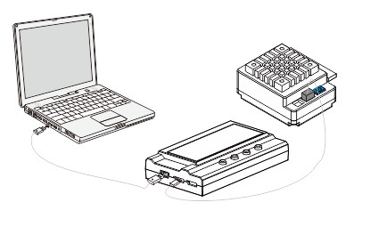
Turbo LCD Program Card
Turbo LCD program card is only applied to Turbo series brushless ESC produced by ROCKET Model. Users can choose their desired parameter at any time. It has 2 use methods as follows: 1. Working as an individual device to set the parameters; 2.Working as an USB adapter to update the firmware and set the parameters on PC.
Specification:
Dimension: 91mm*54mm*18mm (L*W*H)
Weight: 68g
Power supply: DC 5.0V~12.0V
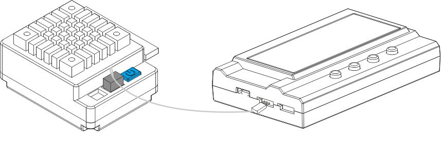
How to connect the LCD program card:
- Disconnect the battery from the ESC;
- Disconnect the signal wire of the ESC from the receiver; then plug it into the socket marked with
- Connect the battery to the ESC and turn on the ESC.
- If the connection is correct, the following message(ROCKET Turbo +Version+Date)will be displayed on the LCD screen. Press any buttons, the following message (Ready to connect ESC)will be showed on the LCD Screen. It signifies that the data connection between LCD and ESC is establishing.
If the data connection between LCD and ESC is failed, the LCD Screen is always showing (Ready to connect ESC); Please check whether the signal wire is connected correctly and repeat step1,2 ,3.
5. If the connection is established successfully, the first programmable item will be displayed on LCD screen. It’s ready to set the parameters now.
Note: Please strictly connect according to the above sequence. The sequence of step 2 and step 3 can not be reversed. Otherwise, the LCD program card will not work properly.
Operation:
l Working as an individual device to program the ESC, the function of button is as follows:
“Menu”: Change the programmable items circularly;
“Value”: Change the parameters of each programmable item circularly
Note: Keeping the “Menu” or “Value” button holding can select the desired parameters quickly.
“Reset”: Return to the default settings
“OK”: Save the current parameters into the ESC. If you don’t press “OK” button, the customized settings will not be saved and updated into the ESC. If you just press ”Menu” button, the customized settings are just saved into the program card, not into the ESC.
For example: Firstly, enter the interface of a customized programmable item (e.g.: cut-off voltage 3.2/cell); Secondly, press “Value” button to select the desired parameters; Thirdly, press “ok” button to save the parameters into the ESC.
- Working as an USB adapter to link the ESC with PC to update the firmware or set the parameters on PC.
Suggested Power Configuration
|
Motor Type |
KV |
FDR(1/10 on-road) |
FDR(1/10 off-road) |
|
3.5T |
9200 |
9.0-11.0 |
|
|
4.5T |
7300 |
8.4-10.0 |
|
|
5.5T |
6100 |
8.0-9.4 |
9.5-11.0 |
|
6.5T |
5200 |
7.4-8.4 |
9.0-11.0 |
|
8.5T |
4000 |
6.0-7.0 |
8.0-9.6 |
|
10.5T |
3300 |
5.0-6.0 |
7.0-8.5 |
|
11.5T |
3000 |
4.5-5.5 |
6.5-8.0 |
|
13.5T |
2600 |
4.0-5.0 |
6.5-7.5 |
|
17.5T |
1900 |
3.8-4.5 |
5.5-7.0 |
|
21.5T |
1600 |
*Above FDR is only applied to use 2S Lipo or 7.2V NiXX battery and zero timing mode.
Free Shipping & Return
Free shipping on all orders over Rs. 2000
Money back guarantee
100% original products
Online support
11pm to 8pm
- Latest Products


-
-
-
-
 Special Price PKR6,315.00 Regular Price PKR8,015.00Out of stock
 -
-
-